
PCB Enclosure Guide for Hardware Engineers

Yang Tianming
Principal Engineer | 21 Years in Sheet Metal Fabrication
My expertise lies in die/mold design and manufacturing and sheet metal process optimization. I focus on technical problem-solving from the tooling source to mass production, driving cost efficiency and quality assurance.
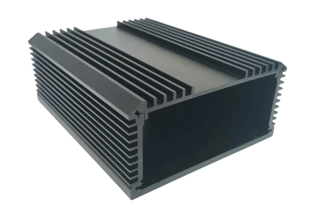
Table of Contents
PCB Enclosure Guide for Hardware Engineers
As hardware engineers, we pour our souls into schematics and board layouts, optimizing traces and component placement. But all this hard work can be undone if we neglect the final, critical component: the PCB enclosure. This guide draws from real-world experience to help you navigate the design and selection of the right electronics enclosure for your project, ensuring your circuit boards survive and thrive in the real world.
1. Introduction: The Critical Role of PCB Enclosures
Think of a PCB enclosure as your product’s suit of armor. It’s the first line of defense against a hostile world. For us engineers, it’s not just a cosmetic box; it’s an integral part of the system that impacts reliability, safety, and user experience.
From my own experience, the common challenges we face include:
Last-Minute Fit Issues: The board we perfectly designed doesn’t fit into the chosen off-the-shelf enclosure due to unaccounted-for connectors or components.
Thermal Catastrophes: A sleek, sealed plastic box turning into an oven because we underestimated the power dissipation of our circuit boards.
EMI Nightmares: A sensitive sensor board failing EMC tests because the electronics enclosure provided no shielding.
Getting the enclosure right from the start saves countless hours of rework and field failures.
2. Basic Functions & Types of PCB Enclosures
A well-chosen enclosure performs multiple critical functions:
Physical Protection: Shields the circuit boards from dust, debris, accidental impact, and unauthorized tampering.
Environmental Sealing: Keeps out moisture, water, and other contaminants, which is defined by its IP (Ingress Protection) rating.
EMI/RFI Shielding: Metal enclosures include this inherent benefit, containing electromagnetic emissions from the board and protecting it from external interference.
Heat Dissipation: Designed with vents, heat sinks, or using thermally conductive materials to manage temperature.
Common types of PCB enclosures we encounter:
Plastic Enclosures: Made from ABS, Polycarbonate, or Nylon. They are cost-effective, lightweight, and offer good electrical insulation. Ideal for consumer electronics and indoor use.
Metal Enclosures: Typically aluminum or steel. They offer superior strength, excellent EMI shielding, and great heat dissipation. Perfect for industrial controls, telecom, and outdoor applications.
Waterproof Enclosures: These feature gaskets and seals to achieve high IP ratings (e.g., IP67), making them suitable for automotive, marine, or outdoor environments.
Thermal Management Enclosures: Designed with integrated heat sinks, fans, or vents specifically for high-power applications like motor drives or LED lighting.
It’s crucial to understand that enclosures include a vast range of structural forms, from simple handheld boxes to complex modular chassis systems.
3. Hardware Engineer’s Perspective: How to Choose the Right Enclosure?
This is where theory meets the benchtop. Here’s a practical framework for selection:
Material Selection: The Core Trade-Off
ABS Plastic:
Pros: Low cost, lightweight, good impact strength, easy to mold into complex shapes.
Cons: Poor UV resistance (can yellow), lower thermal conductivity, offers no EMI shielding.
Polycarbonate (PC):
Pros: High impact resistance and clarity, good heat resistance.
Cons: More expensive than ABS, can be susceptible to chemical attacks.
Aluminum:
Pros: Excellent strength-to-weight ratio, superb heat dissipation, inherent EMI shielding, can be machined or extruded.
Cons: Higher cost, can be prone to scratching, requires grounding considerations.
Structural Design: Think About Assembly
Mounting Methods: How will your board mount inside? Look for enclosures with built-in PCB standoffs, bosses, or DIN-rail mounts. Designing your board with corresponding mounting holes is a critical step often overlooked.
Interface Layout: Plan all panel cut-outs for connectors, switches, and indicators in the CAD stage. There’s nothing more frustrating than trying to hand-file a cut-out for a DB9 connector during assembly.
Heat Dissipation: If you can’t use a metal enclosure, strategic venting is key. Use simulation tools early to identify hot spots and design vents or choose an enclosure that allows for a small fan.
Real-Case Sharing: The Industrial Controller
We once designed a compact industrial controller that initially used a sealed ABS box. During testing, the main regulator overheated, causing thermal throttling. The solution wasn’t a complex board re-spin; it was switching to an aluminum enclosure with a thermally conductive pad between the regulator and the enclosure wall. The case itself became the heat sink, solving the problem cost-effectively.
4. Common Design Mistakes & Solutions
Let’s learn from common pitfalls:
Mistake 1: Poor Thermal Design
Scenario: Packing high-power components in a small, sealed plastic box.
Solution: Always perform a basic thermal analysis. Select an enclosure with adequate surface area or venting. Use thermal interface materials to transfer heat to the enclosure walls.
Mistake 2: Structural Mismatch
Scenario: The board fits, but the height of a tall capacitor or a wired connector prevents the lid from closing.
Solution: Always create a 3D model (STEP file) of your PCB and place it inside the enclosure’s 3D model. This ECAD-MCAD collaboration is non-negotiable in modern design.
Mistake 3: Inadequate Protection Level
Scenario: A product intended for a dusty warehouse fails because dust ingress causes short circuits on the circuit boards.
Solution: Understand IP ratings. For such environments, a minimum of IP54 is often required. Don’t just guess the environment; define it and select the IP rating accordingly.
Conclusion: A Key Step in Building Reliable Electronics
Selecting the right PCB enclosure is not a last-minute packaging decision; it is a fundamental engineering choice that directly impacts the performance, reliability, and longevity of your product. The core principles are simple: define your environmental needs, understand material trade-offs, and collaborate early with mechanical design.
By integrating enclosure considerations from the very beginning of your circuit boards design process, you transition from simply building a functioning board to delivering a robust, professional-grade product. Remember, a well-protected PCB is a reliable PCB.
Q&A: Frequently Asked Questions from PCB Engineers
Q: How to evaluate the protection level of an enclosure?
A: Look for the IP rating code (e.g., IP67). The first digit (6) means “dust-tight.” The second digit (7) means it can withstand temporary immersion in water. For outdoor use, also consider UV resistance (for plastics) and corrosion resistance (for metals).
Q: Will metal enclosures affect signal integrity?
A: Yes, significantly. A metal electronics enclosure acts as a Faraday cage, which is great for EMI. However, it can cause parasitic capacitance if traces or antennas are too close to the metal wall. Always model and test antenna performance and high-speed signals with the enclosure in place.
Q: How to consider scalability and maintainability in enclosure design?
For scalability, consider enclosures that are part of a modular system or can be easily expanded. For maintainability, think about access: use screw-down lids instead of ultrasonic welding, and ensure that field-replaceable components like fuses are easily accessible without disassembling the entire unit.